For my home reverse osmosis (RO) system I wanted real‑time visibility into three things:
- TDS (Total Dissolved Solids) before the RO membrane (tap water / inlet)
- TDS after the membrane (permeate / filtered water)
- How much water actually flows through the system over time (liters per day, month, etc.)
Commercial inline TDS meters usually come as closed black boxes with a tiny display and no way to integrate them into Home Assistant. And while there are quite a few hobby TDS probes for Arduino/ESP, I couldn’t find ready‑made probes that combine both TDS and temperature in a single housing that would look clean in a drinking water installation.
So I decided to hack a commercial RO TDS monitor, salvage its probes, and connect everything to an ESP32‑C6 running ESPHome. 😈
Hardware Overview 🧩
1. Donor device: commercial RO TDS monitor
Since I couldn’t find decent standalone TDS+temperature probes, I bought this ready‑made TDS monitor:
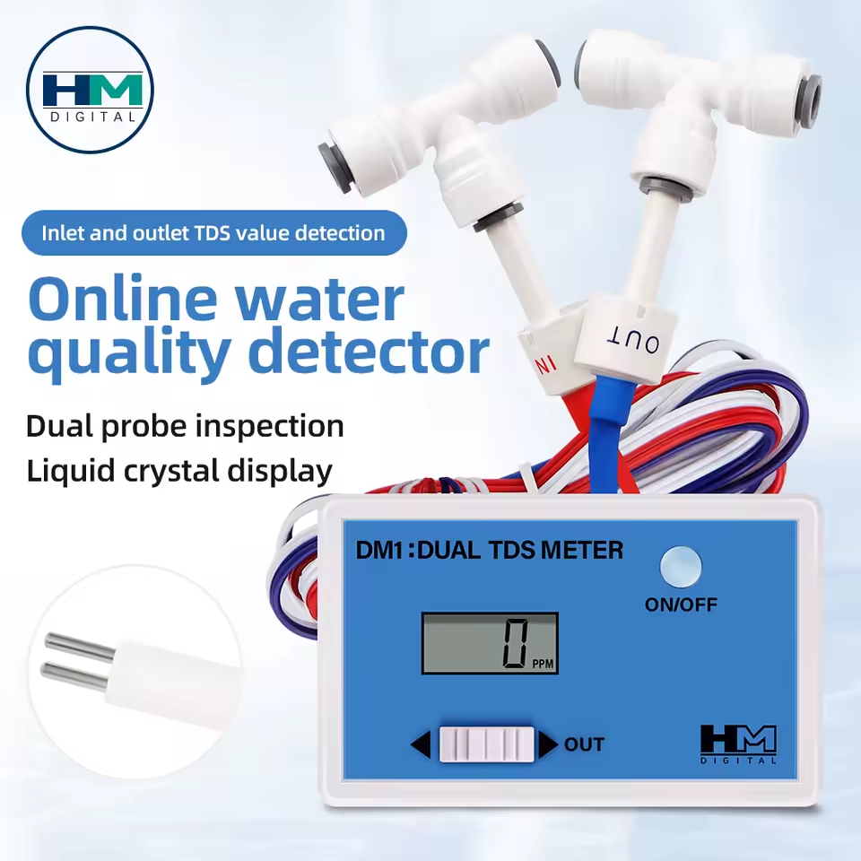
This device has two probes (IN and OUT) in compact plastic housings designed for 1/4″ RO tubing. Inside each probe there is:
- A pair of electrodes for measuring conductivity (TDS)
- A built‑in NTC temperature sensor
The original electronics and LCD were useless for integration, but the probes themselves were exactly what I needed. So I kept the probes and ditched the board.
2. Flow sensor 🚿
To measure how much water passes through the system, I added a Hall‑effect flow sensor (typical YF‑S402B style). It outputs a pulse train proportional to flow rate — more pulses = more liters per minute.
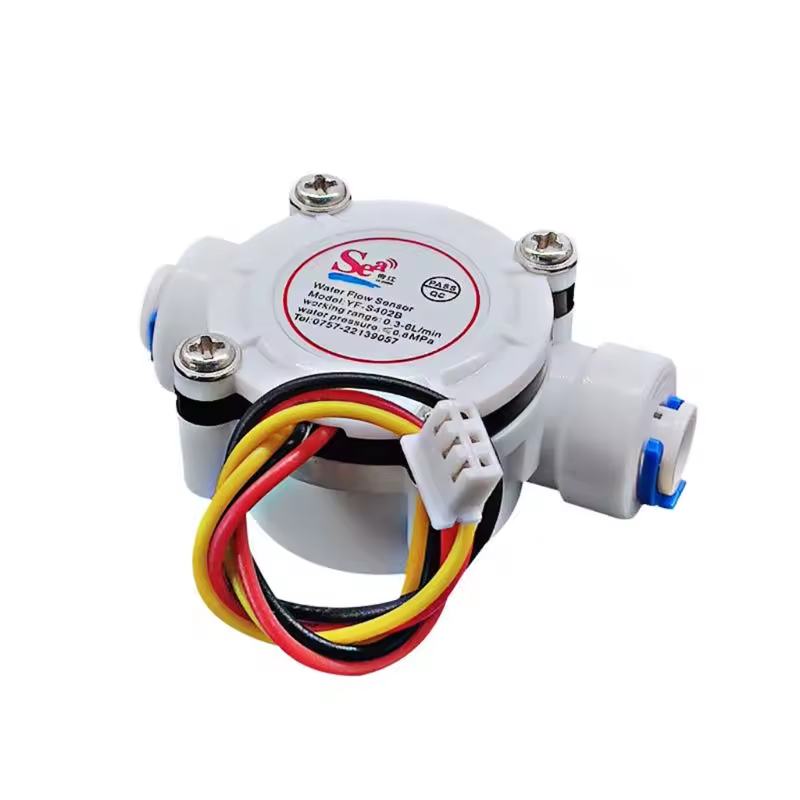
This sensor sits in the inlet line, so I can count the total amount of water processed by the RO system.
3. Plumbing fittings: two T‑connectors 🔧
To install the TDS probes inline, I used two T‑fittings for 1/4″ RO tubing:
- One T‑connector on the inlet line → TDS IN probe
- One T‑connector on the permeate/clean water line → TDS OUT probe
The probes screw into these fittings so the water flows around them, just like in the original commercial TDS monitor.
I didn’t buy these fittings separately — they came bundled together with the probes in the original commercial TDS monitor.
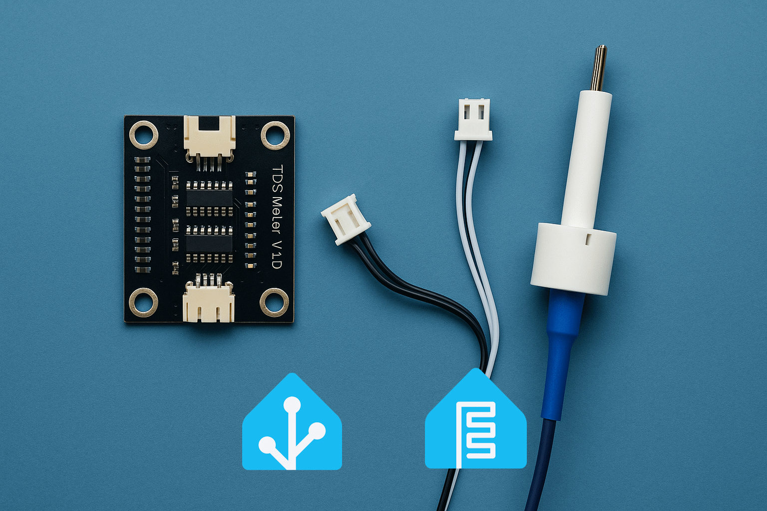
4. TDS amplifier boards 🔌
The probes themselves are just passive components. To read TDS with an ESP32, you need an analog front‑end that excites the probe and outputs a voltage proportional to conductivity.
For that I used TDS meter boards (the classic DFRobot‑style modules):
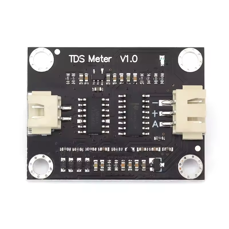
Each board has:
- A connector for the probe
- A BNC or JST interface (depending on the model)
- An analog voltage output (0–3.3 V range)
I use two boards:
- One for TDS IN (raw water)
- One for TDS OUT (filtered water)
Both analog outputs go to different ADC pins of the ESP32‑C6.
5. ESP32‑C6 as the brain 🧠
The controller is:
- An ESP32‑C6 devkit
- Running ESPHome with the
esp-idfframework - Connected to Wi‑Fi and Home Assistant via the native ESPHome API
This single board reads:
- Two TDS voltages (
tds_in_voltage,tds_out_voltage) - Two NTC temperature sensors (inside the probes)
- One pulse flow sensor
And exposes:
- TDS IN / TDS OUT (ppm, temperature‑compensated)
- Temperature IN / OUT (°C)
- Instantaneous flow rate (L/min)
- Total volume (L), persisted across reboots
Reverse Engineering the NTC Sensors 🧪
The tricky part with the probes was figuring out what kind of NTC thermistor is inside and how to turn its resistance into temperature.
Step 1: Identify the wiring
From the donor device and a bit of continuity testing it became clear that:
- The TDS electrodes go to the original meter’s excitation circuitry (colored wires)
- The NTC sensor is a separate pair of leads (white wires)
I wired the NTC from each probe as:
- One side to GND
- The other side to an ADC pin via a fixed 10 kΩ resistor to 3.3 V
So the schematic is:
3.3 V → 10 kΩ resistor → ADC node → NTC → GND
In ESPHome terms this is a DOWNSTREAM configuration (fixed resistor on the high side, NTC to ground).
Step 2: Measuring resistance at a known temperature
With the probes sitting at room temperature, I measured:
- Ambient temp: 26.5 °C (using a trusted thermometer)
- NTC resistance: ≈ 9.06 kΩ at that temperature
That gave me one reference point for the thermistor:
T₀ = 26.5 °CR₀ = 9.06 kΩ
Step 3: Choosing a B‑constant
Most water‑grade epoxy‑potted NTCs are in the 10 kΩ / 3950–4200 K range. I experimentally tested a few B values in ESPHome and observed which curve best matched reality when the probe was:
- In room‑temperature water
- In slightly warmed water
- In cooled water
After some experiments, a B‑constant of 4200 K with R₀ = 9.06 kΩ @ 26.5 °C produced very reasonable readings, so I baked those values into ESPHome:
- platform: ntc
  id: tds_in_temperature
  sensor: ntc_in_resistance
  name: "TDS IN Temperature"
  unit_of_measurement: "°C"
  icon: mdi:thermometer-water
  accuracy_decimals: 0   # Expose integer °C to Home Assistant
  calibration:
    b_constant: 4200
    reference_temperature: 26.5°C
    reference_resistance: 9.06kOhm
  filters:
    - sliding_window_moving_average:
        window_size: 10
        send_every: 1
The same logic is used for tds_out_temperature.
Internally ESPHome still uses floating‑point precision for all calculations; accuracy_decimals: 0 only affects how values are published to Home Assistant.
ESPHome Configuration Breakdown 🧾
Let’s walk through the most important parts of the ESPHome YAML and what each block does.
1. ADC sensors for raw TDS voltages
Each TDS board outputs a voltage proportional to conductivity. These are read with two ADC channels:
- platform: adc
  id: tds_in_voltage
  pin: 3
  attenuation: 11db      # up to ~3.3 V
  update_interval: 200ms
  internal: true
  accuracy_decimals: 3
  filters:
    - median:
        window_size: 7
        send_every: 1
        send_first_at: 1
    - sliding_window_moving_average:
        window_size: 20
        send_every: 5

- platform: adc
  id: tds_out_voltage
  pin: 2
  attenuation: 11db
  update_interval: 200ms
  internal: false
  accuracy_decimals: 3
  filters:
    - median:
        window_size: 7
        send_every: 1
        send_first_at: 1
    - sliding_window_moving_average:
        window_size: 20
        send_every: 5
Key points:
mediancleanup reduces spikes from electrical noise.sliding_window_moving_averagesmooths the signal over ~4 seconds.- For now, only OUT is exposed directly to HA (
internal: false), but you can make IN visible as well if you want.
2. NTC chain: ADC → resistance → temperature 🌡️
Each probe gets three steps in ESPHome:
- Raw ADC read from the NTC voltage divider
- Convert voltage → resistance using the known fixed resistor
- Convert resistance → temperature using the NTC model
Example for TDS IN:
# 1) ADC
- platform: adc
  id: ntc_in_adc
  pin: 4
  attenuation: 6db
  update_interval: 1s
  internal: true
  accuracy_decimals: 4

# 2) Voltage → resistance
- platform: resistance
  id: ntc_in_resistance
  sensor: ntc_in_adc
  configuration: DOWNSTREAM
  resistor: 10kOhm
  internal: true

# 3) Resistance → temperature
- platform: ntc
  id: tds_in_temperature
  sensor: ntc_in_resistance
  name: "TDS IN Temperature"
  unit_of_measurement: "°C"
  icon: mdi:thermometer-water
  accuracy_decimals: 0
  calibration:
    b_constant: 4200
    reference_temperature: 26.5°C
    reference_resistance: 9.06kOhm
  filters:
    - sliding_window_moving_average:
        window_size: 10
        send_every: 1
The same pattern is used for the OUT probe.
3. TDS computation with temperature compensation 💧
Raw voltage is not linearly equal to TDS, and TDS itself depends strongly on temperature. To get reasonably accurate numbers, I used the DFRobot TDS formula with temperature compensation.
The template sensor for TDS IN looks like this:
- platform: template
  id: tds_in_ppm
  name: "TDS IN"
  unit_of_measurement: "ppm"
  icon: "mdi:water-opacity"
  accuracy_decimals: 0
  update_interval: 1s
  lambda: |-
    // 1) Read water temperature (fallback to 25 °C if sensor not ready)
    float waterTemperatureC = id(tds_in_temperature).state;
    if (isnan(waterTemperatureC)) {
      waterTemperatureC = 25.0f;
    }

    // 2) Read compensated voltage from the TDS board
    float voltage = id(tds_in_voltage).state;

    // 3) Apply temperature compensation (2% per °C from 25 °C)
    float compensationCoefficient = 1.0f + 0.02f * (waterTemperatureC - 25.0f);
    float compensatedVoltage = voltage / compensationCoefficient;

    // 4) Apply DFRobot TDS polynomial
    float tds = (133.42f * compensatedVoltage * compensatedVoltage * compensatedVoltage
                 - 255.86f * compensatedVoltage * compensatedVoltage
                 + 857.39f * compensatedVoltage) * 0.5f;

    // 5) Apply calibration factor (found experimentally)
    const float CAL_FACTOR_IN = 0.727f;

    return tds * CAL_FACTOR_IN;
  filters:
    - sliding_window_moving_average:
        window_size: 10
        send_every: 1
For TDS OUT the logic is identical, with its own calibration factor (in my case I ended up using the same 0.727, but you can calibrate them independently).
Calibrating the TDS Sensors 🧪📏
To get meaningful ppm values, you need to calibrate the TDS calculation against a known reference solution.
I used a TDS calibration solution with a known ppm value.
I don’t have a link to buy it online because I purchased it in a local store, but you can Google “TDS calibration solution.”
Calibration procedure
- Prepare the calibration solution according to the manufacturer’s instructions (correct dilution, temperature, etc.).
- Put the IN probe into the solution (or whichever one you want to calibrate first).
- Let it sit for a few minutes so both the probe and the solution reach thermal equilibrium.
- In ESPHome logs / Home Assistant, monitor the raw TDS value before applying
CAL_FACTOR. For example, temporarily set:const float CAL_FACTOR_IN = 1.0f;and note whattdsvalue your code calculates at that point. - Compute the required calibration factor:
CAL_FACTOR = TARGET_PPM / MEASURED_PPMExample: if the solution is 1413 ppm and your raw calculation gives 1943 ppm, then:CAL_FACTOR = 1413 / 1943 ≈ 0.727 - Put that factor into the code:
const float CAL_FACTOR_IN = 0.727f; - Re‑upload the firmware and verify that the reading now matches the calibration solution.
Repeat the same process for the OUT probe if you want separate calibration.
Flow Sensor and Volume Integration 🚿📊
The flow sensor produces pulses at a rate proportional to flow. The spec usually gives a relation like:
F(Hz) = K × Q(L/min)
or in terms of pulses per liter.
In my case, the theoretical spec was around 2280 pulses per liter, but real‑world measurements showed a significant discrepancy (for 1 liter of water, the system was reporting only about 0.718 L).
So I calibrated it empirically.
Flow calibration procedure
- Connect the flow sensor in series with your RO inlet line.
- Configure a temporary ESPHome sensor that simply counts pulses and computes liters based on your initial assumption (
pulses_per_liter = 2280). - Run exactly 1 liter of water through the system into a measuring container.
- Check what ESPHome says:
- If it shows e.g. 0.718 L instead of
1.000 L, then yourpulses_per_literis too high.
- If it shows e.g. 0.718 L instead of
- Compute the actual pulses per liter:
pulses_per_liter_real = pulses_per_liter_initial × (measured_volume / real_volume) pulses_per_liter_real = 2280 × (0.718 / 1.0) ≈ 1637 - Update the ESPHome config to use this new factor.
In the final version, my pulse_counter sensor looks like this:
- platform: pulse_counter
  id: water_in_flow_l_min
  name: "Water In Flow Rate"
  pin:
    number: 6
    mode:
      input: true
      pullup: true
  unit_of_measurement: "L/min"
  icon: "mdi:water-pump"
  update_interval: 1s
  accuracy_decimals: 2
  filters:
    # pulses_per_min / 1637 ≈ L/min
    - multiply: 0.00061086   # 1 / 1637
Now the instantaneous flow reading in L/min matches reality much better.
Integrating total volume over time 🧮
To track how many liters have passed through the RO system, I use ESPHome’s integration sensor:
- platform: integration
  id: water_in_total_l
  name: "Water In Total"
  sensor: water_in_flow_l_min
  time_unit: min
  unit_of_measurement: "L"
  device_class: water
  state_class: total_increasing
  accuracy_decimals: 2
  integration_method: trapezoid
  restore: true
Important details:
- The input is in L/min, and we integrate over minutes, so the result is in liters.
state_class: total_increasingmakes this sensor compatible with Home Assistant’s energy/utility dashboards.restore: trueensures the total volume survives reboots (saved in flash).
In Home Assistant, I then create Utility Meter entities for daily, monthly, and yearly water consumption using this Water In Total sensor as the source.
Integration with Home Assistant 🏠💙
With ESPHome’s native API, the ESP32‑C6 shows up in Home Assistant as a device with multiple entities:
TDS IN(ppm)TDS OUT(ppm)TDS IN Temperature(°C)TDS OUT Temperature(°C)Water In Flow Rate(L/min)Water In Total(L)
On top of that you can define in Home Assistant:
- Daily/Monthly/Yearly water usage via
utility_meter - Automations that:
- Alert you when TDS OUT rises above a threshold (e.g. filter needs replacement)
- Notify you when you’ve used more than X liters per day
- Track long‑term stats and visualize TDS and usage trends
All of this works over Wi‑Fi with no cloud dependencies.
Lessons Learned & Final Thoughts 💡
This project started because I couldn’t find nice, compact probes that combine TDS + temperature in a way that fits into standard RO plumbing and exposes data to my smart home.
By salvaging probes from a commercial TDS monitor and pairing them with:
- TDS amplifier boards
- A Hall‑effect flow sensor
- ESP32‑C6 + ESPHome
…I ended up with a fully local, highly customizable RO monitoring system that:
- Measures both input and output water quality
- Compensates TDS readings for temperature
- Tracks water consumption over time
- Integrates cleanly with Home Assistant
If you’re comfortable with basic electronics and plumbing, this is a very satisfying project that gives you deep insight into how your RO system performs over time — and when it’s really time to change those filters instead of just guessing. 😉
You can easily extend this setup further:
- Add leak sensors for safety 🔔
- Control RO pump via a smart relay 💡
- Log all data to InfluxDB and build Grafana dashboards 📊
For me, the combination of ESPHome + ESP32‑C6 + a bit of hardware hacking turned an opaque black‑box water filter into a transparent, observable system that I can trust and analyze.
The full source code is also available on GitHub as well.
esphome:
  name: reverse_osmosis_meter
  friendly_name: Esp32C6 Reverse Osmosis TDS and Flow Meter

esp32:
  board: esp32-c6-devkitc-1
  framework:
    type: esp-idf

# Enable logging
logger:

# Enable Home Assistant API
api:
  encryption:
    key: !secret reverse_osmosis_meter_encryption_key

ota:
  - platform: esphome
    password: !secret reverse_osmosis_meter_encryption_key

wifi:
  ssid: !secret wifi_ssid
  password: !secret wifi_password

  # Enable fallback hotspot (captive portal) in case wifi connection fails
  ap:
    ssid: "Esp32C6-Tds-Meter"
    password: "uhv4aaRh8c3Q"

captive_portal:

debug:
  update_interval: 5s

text_sensor:
  - platform: debug
    device:
      name: "Device Info"
    reset_reason:
      name: "Reset Reason"

sensor:
  # ---------- TDS VOLTAGE SENSORS (IN / OUT) ----------

  # Raw ADC for TDS IN (voltage)
  - platform: adc
    id: tds_in_voltage
    pin: 3                # TDS IN analog output
    attenuation: 11db     # full range up to ~3.3V
    update_interval: 200ms
    internal: true       # temporary visible in HA for diagnostics
    accuracy_decimals: 3
    filters:
      - median:
          window_size: 7
          send_every: 1
          send_first_at: 1
      - sliding_window_moving_average:
          window_size: 20   # ~4 seconds smoothing (20 * 0.2s)
          send_every: 5     # send to HA roughly once per second

  # Raw ADC for TDS OUT (voltage)
  - platform: adc
    id: tds_out_voltage
    pin: 2                # TDS OUT analog output
    attenuation: 11db
    update_interval: 200ms
    internal: true
    accuracy_decimals: 3
    filters:
      - median:
          window_size: 7
          send_every: 1
          send_first_at: 1
      - sliding_window_moving_average:
          window_size: 20
          send_every: 5

  # ---------- NTC FOR TDS IN ----------

  # ADC for NTC in TDS IN probe
  - platform: adc
    id: ntc_in_adc
    pin: 4                # GPIO for NTC (IN)
    attenuation: 6db
    update_interval: 1s
    internal: true
    accuracy_decimals: 4

  # Convert ADC -> resistance (NTC downstream: 3.3V -> 10k -> node -> NTC -> GND)
  - platform: resistance
    id: ntc_in_resistance
    sensor: ntc_in_adc
    configuration: DOWNSTREAM
    resistor: 10kOhm       # fixed resistor from 3.3V to node
    internal: true

  # NTC temperature for TDS IN
  - platform: ntc
    id: tds_in_temperature
    sensor: ntc_in_resistance
    name: "TDS IN Temperature"
    unit_of_measurement: "°C"
    icon: mdi:thermometer-water
    accuracy_decimals: 0   # Send integer °C to Home Assistant
    calibration:
      b_constant: 4200
      reference_temperature: 26.5°C
      reference_resistance: 9.06kOhm
    filters:
      - sliding_window_moving_average:
          window_size: 10
          send_every: 1

  # ---------- NTC FOR TDS OUT ----------

  # ADC for NTC in TDS OUT probe
  - platform: adc
    id: ntc_out_adc
    pin: 5                # GPIO for NTC (OUT)
    attenuation: 6db
    update_interval: 1s
    internal: true
    accuracy_decimals: 4

  - platform: resistance
    id: ntc_out_resistance
    sensor: ntc_out_adc
    configuration: DOWNSTREAM
    resistor: 10kOhm
    internal: true

  - platform: ntc
    id: tds_out_temperature
    sensor: ntc_out_resistance
    name: "TDS OUT Temperature"
    unit_of_measurement: "°C"
    icon: mdi:thermometer-water
    accuracy_decimals: 0   # Send integer °C to Home Assistant
    calibration:
      b_constant: 4200
      reference_temperature: 26.5°C
      reference_resistance: 9.06kOhm
    filters:
      - sliding_window_moving_average:
          window_size: 10
          send_every: 1

  # ---------- TDS CALCULATIONS (IN / OUT) ----------

  # Calculated TDS for IN (ppm)
  - platform: template
    id: tds_in_ppm
    name: "TDS IN"
    unit_of_measurement: "ppm"
    icon: "mdi:water-opacity"
    accuracy_decimals: 0
    update_interval: 1s
    lambda: |-
      // Water temperature from NTC (IN). Fallback to 25°C if not ready.
      float waterTemperatureC = id(tds_in_temperature).state;
      if (isnan(waterTemperatureC)) {
        waterTemperatureC = 25.0f;
      }

      // Voltage from ADC (already in Volts)
      float voltage = id(tds_in_voltage).state;

      // Temperature compensation (2% per °C from 25°C)
      float compensationCoefficient = 1.0f + 0.02f * (waterTemperatureC - 25.0f);
      float compensatedVoltage = voltage / compensationCoefficient;

      // Base TDS formula (DFRobot polynomial)
      float tds = (133.42f * compensatedVoltage * compensatedVoltage * compensatedVoltage
                   - 255.86f * compensatedVoltage * compensatedVoltage
                   + 857.39f * compensatedVoltage) * 0.5f;

      // Calibration factor for IN
      const float CAL_FACTOR_IN = 0.727f;

      return tds * CAL_FACTOR_IN;
    filters:
      - sliding_window_moving_average:
          window_size: 10
          send_every: 1

  # Calculated TDS for OUT (ppm)
  - platform: template
    id: tds_out_ppm
    name: "TDS OUT"
    unit_of_measurement: "ppm"
    icon: "mdi:water-opacity"
    accuracy_decimals: 0
    update_interval: 1s
    lambda: |-
      float waterTemperatureC = id(tds_out_temperature).state;
      if (isnan(waterTemperatureC)) {
        waterTemperatureC = 25.0f;
      }

      float voltage = id(tds_out_voltage).state;

      float compensationCoefficient = 1.0f + 0.02f * (waterTemperatureC - 25.0f);
      float compensatedVoltage = voltage / compensationCoefficient;

      float tds = (133.42f * compensatedVoltage * compensatedVoltage * compensatedVoltage
                   - 255.86f * compensatedVoltage * compensatedVoltage
                   + 857.39f * compensatedVoltage) * 0.5f;

      const float CAL_FACTOR_OUT = 0.727f;

      return tds * CAL_FACTOR_OUT;
    filters:
      - sliding_window_moving_average:
          window_size: 10
          send_every: 1

  # ---------- WATER FLOW SENSOR (YF-S402B) ----------

  # Flow rate in L/min
  - platform: pulse_counter
    id: water_in_flow_l_min
    name: "Water In Flow Rate"
    pin:
      number: 6              # GPIO for yellow wire from flow sensor
      mode:
        input: true
        pullup: true         # use internal pull-up to 3.3V
    unit_of_measurement: "L/min"
    icon: "mdi:water-pump"
    update_interval: 1s
    accuracy_decimals: 2
    filters:
      # Spec: F(Hz) = 38 * Q(L/min)  =>  ~2280 pulses per liter
      # pulse_counter дає pulses/min, тому:
      #   Q(L/min) = pulses_per_min / 2280
      # Calibrated: ~1637 pulses per liter  =>  L/min = pulses_per_min / 1637
      - multiply: 0.00061086

  # Integrated total volume in liters, stored across reboots
  - platform: integration
    id: water_in_total_l
    name: "Water In Total"
    sensor: water_in_flow_l_min
    time_unit: min           # integrate L/min over minutes => liters
    unit_of_measurement: "L"
    device_class: water
    state_class: total_increasing
    accuracy_decimals: 2
    integration_method: trapezoid
    restore: true            # store value in flash so it survives reboot
Leave a Reply